Coupling and stands
Last time I got the software side of the build together. Now is it time to connect all the hardware more permanently. The most interesting connection is the coupling between the motor and the hand of the weight. The hand gets turned by a rack and pinion mechanism. With the rack connected to the tray (linear motion) and the pinion on the shaft connected to the hand. The pinion was a perfect place to couple the motor onto. (Almost as is it was its purpose..) So I used the gear plugin in freecad1, made one wit same pitch and tooth count2 as the one connected to the hand, and cut it out of a cylinder body with a cutout for the motor shaft. The motor had one of those shafts that had been cut on two side (right side in picture below).

Left the cutout for the pinion on the “hand shaft”. Right the hole for the motor shaft.
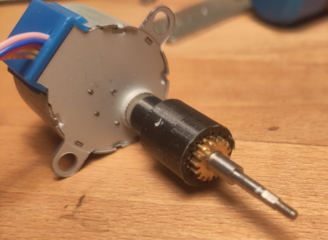
Here the printed coupling.
Next was to make some brackets for the motor and button. There was a bracket, that supported the shaft for the hand. With the motor supporting the shaft through the coupling, that was redundant. So I made a bracket that could be mounted with the screws for the redundant bracket, and keep the motor in the right distance.
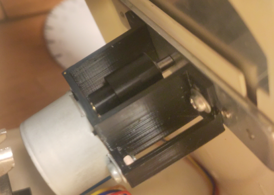
Difficult angle to get a good picture, but here is motor mounted at its final place.
The button needed one too. With just the right height to fit the movement of the tray.
Both were simple designs, and 3D printed.
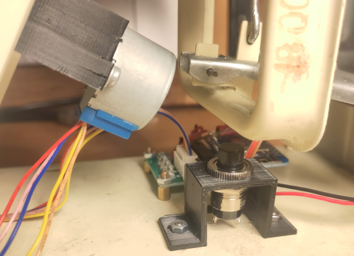
The motor and button mounted with brackets, and electronics in background. Red and black wire is going to a barrel plug in back of the scale for power.
Last thing was to mount thee MCU, driver board and power connector. There is a diagram showing the connections in the repo. But it’s really simple. The motor connected to its driver board, the driver board to MCU and button to the MCUs GPIO, and power connector to the MCUs 5v pin. A ESP8266 can be a bit picky about IO, but I remember it as one of the first few tries worked out.
Last thing is to decide on (and make) a more permanent face for the clock. Right now is it a paper cutout. I’m trying to decide on a design. But I think that I’m almost there.
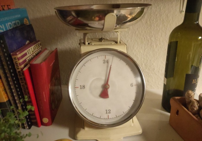
The clock in its “Alpha release”. I should probably try to polish the acrylic front plate too..
Next post will be a round up of the applying of the face, and finished build. Thank you for reading along!
-
Thank you to This old tony for making understanding gears fun. ↩︎